Monday, June 16, 2014

Let there be Light-shafts !

Light is all around us. Our brains are CPU's,  processing mostly light signals. Simulating some lighting effects in 3D applications is not a trivial task. Fortunately, some effects can be simulated dynamically with relatively small computing power with a pretty satisfactory result.
As I already have all the necessary ingredients as a side effect of possessing a deferred renderer, I tried to used them to make a simple light-shaft effect. This lighting effect appears when light travels trough a foggy, dusty, full of small particles medium like air, water or pure industrial smog. The shadow of objects blocking light become visible not only on shaded surfaces, but also on the medium. These are so called light-shafts, God Rays or whatever you like to call them.
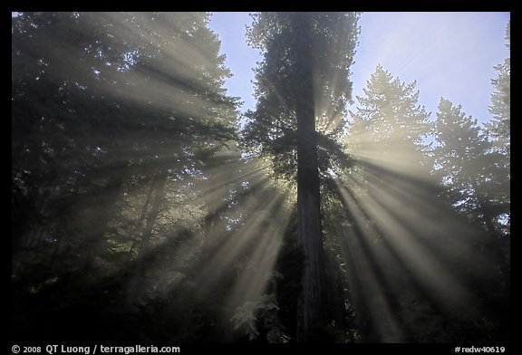


Several approaches to achieve this effect exists in real-time applications and games. Some of them render bright parts of the scene into a small render target, then blur the resulting bright pixels towards the light 2D position and blend the result with the final frame buffer.
Having access to the scene depth buffer and light depth buffer, there is a simple technique that could be used to achieve similar results without presenting the limitations that the above technique suffers.

Trace a ray, starting from eye position in world space toward the scene for every pixel on the scene. This could be optimized greatly by downscaling, bluring and upscaling.
Advance the ray position by a small step and for every step, check to see if that world position can see the light. If it can see it, make it a bit brighter for every step, thus accumulating light and make it appear as small airborne particles reflect more and more light toward the observers eye. For the most part, there are 2 precision aspects you may be concerned. The one is the precision you sample the scene -i.e. do you need to sample the scene for every pixel or "sparse" it a bit, or even do it on a downscaled target. And the second one is how big are your steps toward the scene, and haw many samples you take per ray. In the example bellow I make 64 steps per ray.

Warning HLSL ahead, but the code is pretty simple and it doesn't use advance modern features, so it should be doable in every old version of most shading languages.
 
   float3 currentTestWorldPos = eyePos ; //start with eye's position
   float3 currentRayDir = normalize(vWorldPos.xyz - eyePos) * 2.0f ; //scale it a bit. This can step 2 units further //for every step, from eye position to current pixel position in world space.
 

  for(int i = 0 ; i < 64 ; i++ )
  {
        currentTestWorldPos += currentRayDir ; //advance further

  float3 currentLightDirection = currentTestWorldPos - c_vLightPos.xyz  ; // optain direction to light source for every //test position
  float currentDistance = length(currentLightDirection.xyz);
  currentLightDirection.xyz = currentLightDirection.xyz / currentDistance; //normalize

   //sample depth from cubic shadow map                           
     float currentshadowMapDepth = texCUBE(cubeShadowMapSampler, float4((currentLightDirection.xyz), 0.0f)).x;
  //depth comparison
  if(currentDistance  < (currentshadowMapDepth + 1 ))  
  {
    color *= 1.07f; //make it a bit brighter
  }
 
           //not really necessary, but could be useful in some situations to add contrast.
           else { color *= 0.98f; }//make it a bit darker
  }

Here is how it looks statically and dynamically


Friday, February 28, 2014

The importance of global illumination

Every modern graphics engine needs a global illumination solution. Rage AFAIK uses some kind of path tracing + some static lighting baked into textures(kinda like the good old lightmapping) as they have "inlimited" amount of texture memory. Unreal and other big boys, as DICE use Enlighten, CryTek have their Light Propagation Volumes.
My solution isn't  that advanced, but can be tweaked to look OK. The main drawback of it is that the lighting is static.


Tuesday, February 25, 2014

3ds max - Office chair speed modeling.

I continue to play with 3ds max.
An attempt to model an office chair.


And here is the ingame test of the textured model.


Monday, February 24, 2014

Learning to crawl with 3ds max

For the needs of some of my hobby projects I often have a need for specific assets and level geometry.


Thursday, February 20, 2014

SSAO - Screen Space Ambient Occlusion

In computer graphics, ambient occlusion is used to represent how exposed each point in a scene is to ambient lighting. So the enclosed inside of a tube is typically more occluded (and hence darker) than the exposed outer surfaces; and deeper inside the tube, the more occluded (and darker) it becomes. The result is diffuse, non-directional lighting throughout the scene, casting no clear shadows, but with enclosed and sheltered areas darkened. In this way, it attempts to approximate the way light radiates in real life, especially off what are normally considered non-reflective surfaces.
Unlike local methods like Phong shading, ambient occlusion is a global method, meaning the illumination at each point is a function of other geometry in the scene. However, it is a very crude approximation to full global illumination. The soft appearance achieved by ambient occlusion alone is similar to the way an object appears on an overcast day.

I'm toying with the screen-space approximation of this technique in my Isle of marooned project.
It suffers some limitations and artifacts, that I will discuss and provide more info about in further posts.


Wednesday, February 19, 2014

Global Illumination - lifting the curtain

As promised, I will elaborate on the topic of global illumination and provide a bit of source code to illustrate the method, mentioned in a previous post.
Light probes are spread across critical areas, manually or automatically. Incoming lighting at these points in space is captured in cube maps which are then converted to spherical harmonics.
A short video shows these probes in action


The HLSL code for sampling the spherical harmonics coefficients looks like this :

You provide a normal direction and the function returns the illumination coming from that direction.
 
// 'lightingSH' is the lighting environment projected onto SH (3rd order in this case),

// and 'n' is the surface normal

float3 ProjectOntoSH9(in float3 lightingSH[9], in float3 n)

{

    float3 result = 0.0f;


    // Cosine kernel

    const float A0 = 1.0f;

    const float A1 = 2.0f / 3.0f;

    const float A2 = 0.25f;


    // Band 0

    result += lightingSH[0] * 0.282095f * A0;


    // Band 1

    result += lightingSH[1] * 0.488603f * n.y * A1;

    result += lightingSH[2] * 0.488603f * n.z * A1;

    result += lightingSH[3] * 0.488603f * n.x * A1;


    // Band 2

    result += lightingSH[4] * 1.092548f * n.x * n.y * A2;

    result += lightingSH[5] * 1.092548f * n.y * n.z * A2;

    result += lightingSH[6] * 0.315392f * (3.0f * n.z * n.z - 1.0f) * A2;

    result += lightingSH[7] * 1.092548f * n.x * n.z * A2;

    result += lightingSH[8] * 0.546274f * (n.x * n.x - n.y * n.y) * A2;


    return result;

}


Here is the code for rendering the light probes (for debug purpose)
technique RenderSH
{
    pass p0
 {
  VertexShader = compile vs_3_0 SimpleVSTransformed();
  PixelShader = compile ps_3_0 psLightingRenderSH();
        CullMode = CCW;
  FillMode = solid;
  Zenable = true;
  StencilEnable = true;  
  AlphaBlendEnable = false;
  AlphaTestEnable = false; 
  ZWriteEnable = true; 
 }
};
void SimpleVSTransformed(in float4 inPos: POSITION, in float2 inTex: TEXCOORD0, 
out float4 outPos: POSITION, out float2 outTex: TEXCOORD0, out float4 wPos : TEXCOORD1)
{
outPos = inPos;
outTex = inTex;


outPos = mul(float4(inPos.xyz, 1), c_mViewProjection);
wPos = mul(float4(inPos.xyz, 1), c_mWorld); ; 


}
float4 psLightingRenderSH(PS_INPUT_LIGHT i, in float4 wPos : TEXCOORD1 ) : COLOR0
{


float4 color = 1.0 ;


 float3 vLightDir = normalize(   wPos.xyz - lightProbePos ) ;

   float4 probeCol = float4(ProjectOntoSH9(SHarmonicsCoefficients,-vLightDir) , 1.0) ; 
            return float4(probeCol.xyz  , 1.0);


}
As you can see, a sphere mesh is rendered and this is what is happening, briefly :
 Running through the vertex shader, world space vertex positions (yep, a sphere mesh has vertices spread around the center) are send to the pixel shader via TEXCOORD1 slot. Pixel shader then runs through every pixel, gets the light probe position we are currently rendering, gets the pixel position in world space, subtracts those to form direction and samples the spherical harmonics coefficients to obtain the pixel color.

Tuesday, February 18, 2014

Epic battery eater!

Android is designed (among other things) as a platform for gaming too, although probably not the ideal one.
Still development environments and especially emulators are not at a level sufficient to develop performance critical applications such as games. One way or another, you are forced to go through the slow and tedious process of building the application and uploading it to a a real device if you want to see it in action with more that 5 FPS.
In this regard libraries as libGDX are excellent tools to quickly prototype small games and multimedia applications, and why not a regular mobile application, rich of heavy GUI and graphics.
The framework provides an environment for rapid prototyping and fast iterations. Instead of deploying to Android/iOS/Javascript after each code change, you can run and debug your game on the desktop, natively. Desktop JVM features like code hotswapping reduce your iteration times considerably.
Yeah, for speeding things up, iterations need to be reduced and optimized for speed at code level, and at development cycle level as well. This does not mean that the iterations are the root of all evil.
Here's a quick peek of a small hill-climb racing game. It's meant to run on 

  • Windows
  • Linux
  • Max OS X
  • Android (+2.2)
  • BlackBerry
  • iOS
  • Java Applet (requires JVM to be installed)
  • Javascript/WebGL


Time to show some source code for people who would have been interested to see how the track is generated. It's not pretentious in any way - it's a quick and dirty solution. I actually switched to more natural, hand made "terrains" that are loaded from file and authored in a level editor-like application, where you can define points manually for better control.


    vertexCount = 500 ; 
    float fRoughness = 0.5f;
    
    float vert[] = new float [vertexCount] ; 
    
    for(int i = 0 ; i < vertexCount ; i++ )
    {
   
     vert[i] = i ;
     //if(i % 2 == 0) vert[i] *= scaleX ;
     
     if( i %  2 != 0) vert[i] =  (float) (Math.sin( Math.random()) * 0.9f) * fRoughness ;    
     
    }
Now, for every vertex, texture coordinates are assigned, and every second vertex is send to the bottom of the screen to form the track base.
Vector2 v2 [] = new Vector2[4] ;
  v2[0] = new Vector2(0.0f,0.0f) ; 
  v2[1] = new Vector2(0.5f,1.0f) ;
  v2[2] = new Vector2(1.0f,0.0f) ;
  v2[3] = new Vector2(1.0f,1.0f) ;
  
      
     float meshVertices [] =  new float [vertexCount  * 6 ] ;
     for(int  i = 0 ; i < vertexCount ; i++ )
     {

      meshVertices [ (i*6) + 0 ] = i * scaleX - scaleX  ; 
       
       
      if(i%2==0)
      {
       meshVertices [ (i*6) + 1 ] = -1.0f ;
      }
      else
      {
       meshVertices [ (i*6) + 1 ] = vert[i] ;
       
      }


      meshVertices [ (i*6) + 2 ] = 0.0f  ;
      meshVertices [ (i*6) + 3 ] = Color.toFloatBits(255, 255, 128, 255) ;
      
      int k = i % 4 ; 
      meshVertices [ (i*6) + 4 ] = v2[k].x ;
      meshVertices [ (i*6) + 5 ] = v2[k].y ;


     }
If you are interested to see how the ground track texture looks like, here it is. Use it on your own disk(risk?)